[BACK]
Linking!
How does it work?
What's it for?
"Linking" is a feature that allows you to connect MULTIPLE boards to create larger, more
complex traffic signal configurations.
For example, if you only have a single 3-light signal such as this
one...
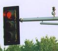 ...perhaps along with one of these...
...you would not need the linking
feature because all that is required to run a signal like this is a single SYNC-5 board that is SELF-LINKED.
But if you want to control a 4-way traffic signal such as one of these: or
possibly these
or
possibly these 
...you can LINK 2 boards together to control the two directions.
Thinking about adding a set of turn arrows? Link a third board!
You can link to your hearts content, as many boards as your application
requires.
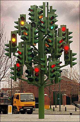
Thinking about building one of these?  (click pic
for larger image) ...not a problem!
(click pic
for larger image) ...not a problem!
How the link connector works
The link connector consists of two screw terminals labeled LINK IN and
LINK OUT. The board normally starts on it's GREEN CYCLE
(see also SLAVE/MASTER
mode). After it cycles through it's RED cycle, it sends a signal
out the LINK-OUT terminal, indicating that it
has completed it's three cycles. The next "linked" board would
receive
this "signal" on it's LINK IN terminal and begin it's
green-yellow-red
cycle. Once that board completes it's red cycle, it sends a
signal out of
it's LINK OUT to trigger the next board, and so on.
You can also have the LINK OUT of one board trigger the LINK IN on
multiple boards for some exotic configurations.
Note: Once a board has completed it's red cycle, and send it's
signal out it's LINK OUT terminal, it will remain RED until it receives
a signal
on it's own LINK IN terminal. Therefore, the last board in the
chain
should have it's LINK OUT connected to the first boards LINK IN to
complete
the loop. Click here for a visual
wiring example.