SYNC-5
EXPANDABLE
Traffic Light Signal Sequencer / Controller with Walk/Don't-Walk Outputs
For single, 2-way, 4-way, 8-way, ANY-way configurations
(emulation use only)
Wiring Instructions in PDF format
EXPANDABLE
Traffic Light Signal Sequencer / Controller with Walk/Don't-Walk Outputs
For single, 2-way, 4-way, 8-way, ANY-way configurations
(emulation use only)
| [Wiring Reference] | [Linking Boards] | [Setting Slave/Master Mode] |
[Setting Light Times] | [Changing Caution Modes] |
| [Alternate Firmware] | [Light Sequence] | [Contact us] | [Home] | [Answers] |
Wiring Instructions in PDF format
| Features: |
| LINK In /
Out screw terminals allows multiple boards to be "Linked / Chained"
to
create 2-way, T-Intersections, 4-way or even 8-way
configurations. |
| ALL Screw Terminals, no soldering required |
| Compact
Size: 3" X 2-1/2" |
| 100 Watts Max per output channel |
| Simple-to-use Single-Button time setting |
| Retains timing / settings after power is removed |
| 4 Caution Modes: RED
YELLOW R/Y Alternate RED flashes, Walk/Don-t Walk Alternate (Wig Wag) |
|
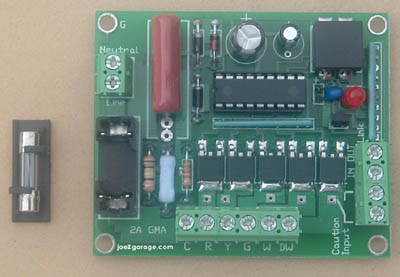
Bring your traffic signal to life with
this traffic-controller /
sequencer circuit board. This circuit boards has 5 outputs: GREEN,
YELLOW, RED, WALK, DON'T-WALK
Each lights timing can be set differently, with a possible range of 1/4 second to 25 minutes PER LIGHT. Connecting the CAUTION INPUT screw terminals together engages 1 of 4 user-selectable CAUTION MODES. Removing the connection will return the board to normal sequence operation. There is a user replaceable fuse. Fuse type is GMA 2 Amp 125/250VAC available from any local electronic store. Sequence of operation: Timing duration for each step is fully adjustable / settable, from 1 sec. to 10 minutes. Step 1: The units starts off with WALK green output ON as well as signal green on Step 2: walk green turns off, DON'T WALK red starts flashing (signal is still green) Step 3: Signal turns YELLOW, and DON'T WALK red goes solid (both occur at the same time) Step 4: Signal turns RED, DON'T WALK red is still solid. Cycle to Step 1 (for a single board) If TWO (or more) boards are linked: After step 4's timing cycle is complete, it sends a signal to BOARD #2 (or next board) through the LINK CONNECTION to begin it's 4 cycles. Once BOARD #2 (or last board in chain) completes it's four steps, it sends a signal back to BOARD #1 through the same LINK CONNECTION to start it's 4 steps all over again, and the entire cycle repeats. |
| Controller / Sequencer Specifications | |
| Range (Min - Max) | |
| Operating Voltage: | 108 - 120 VAC |
| Output
Channels: |
3 signal: green,
yellow, red 2 pedestrian: Walk , Don't-Walk |
| Wattage per output channel: | 100 watts MAX @ 120VAC
(fuse protected) |
| Walk Green Timing Range: |
From 1/2 second to 25 MINUTES |
| Don't-Walk (flashing) Timing
Range: |
From 1/2 second to 25 MINUTES |
| Green Light Timing: | From 1/2 second to 25 MINUTES |
| Yellow Light Timing Range: | From 1/2 second to 25 MINUTES |
| Red Light Timing Range: | From 1/2 second to 25 MINUTES |
| 4 Caution Modes: | Flashing
RED Flashing YELLOW R/Y Alternate RED flashes, Walk/Don't-Walk outputs Alternate (Wig Wag) |
| Board Dimensions (L x W x H): | 3" x 2-1/2" x 1" |